Unlocking the Secrets of the 3 Post Starter Solenoid Wiring Diagram
Ever stared under the hood, bewildered by a tangle of wires? Felt the frustration of a car that just won't crank? The mystery of the 3 post starter solenoid, a crucial component in your vehicle's starting system, often lies at the heart of these automotive woes. Let's unravel this enigma and empower you to tackle starting issues head-on.
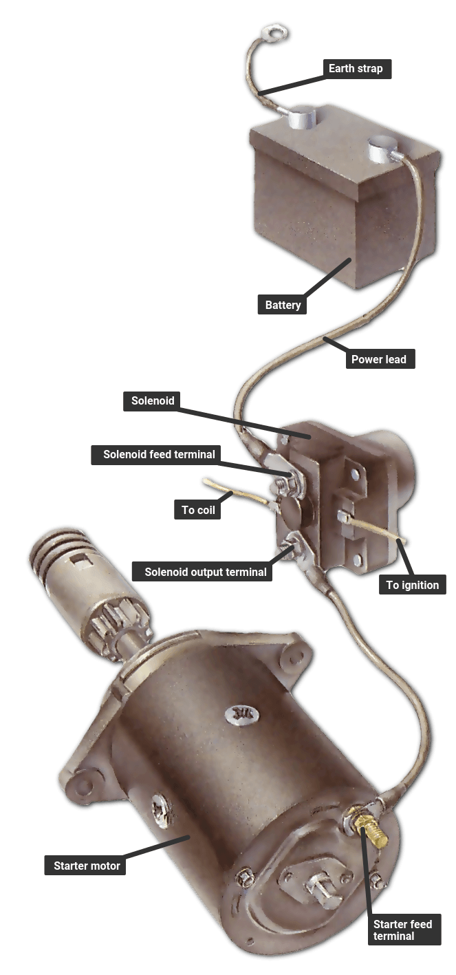
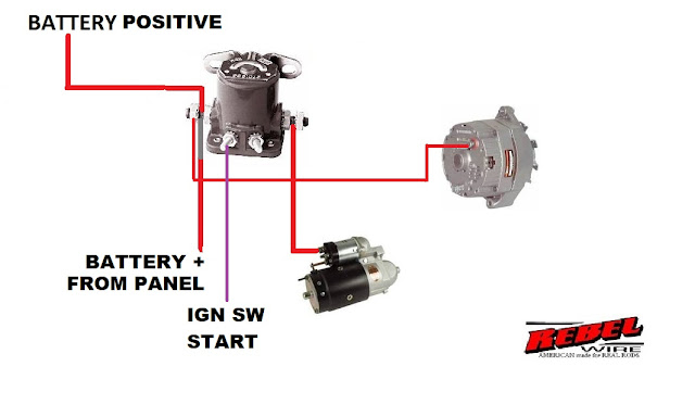
A three-post starter solenoid wiring schematic is essentially a roadmap for the electrical flow that kickstarts your engine. It dictates how power travels from the battery, through the ignition switch, and ultimately to the starter motor. Understanding this flow is fundamental to diagnosing and fixing starting problems. It's like knowing the plumbing of your house – crucial when a pipe bursts!
The solenoid acts like a powerful electrical switch. When you turn the key, it engages, sending a surge of power to the starter motor. This motor then spins the engine, bringing it to life. But what distinguishes the three-post version? The third post offers more control, often used for accessories or safety features. It's like having an extra switch in your electrical circuit, providing greater flexibility.
Historically, starter solenoids have evolved from simpler designs. The three-post configuration emerged as a more versatile solution, allowing for integrated features and improved reliability. Think of it as a refinement of the original, like upgrading from a rotary phone to a smartphone – while the core function remains the same, the added capabilities significantly enhance its usefulness.
Misunderstanding the 3 post starter solenoid wiring can lead to various headaches. From a simple click when you turn the key to a complete no-start situation, incorrect wiring can immobilize your vehicle. It’s like trying to bake a cake with the wrong ingredients – you might get something, but it won't be what you expected. A clear grasp of the wiring diagram is vital for smooth engine starts and avoiding potential electrical damage.
A 3-post starter solenoid wiring diagram typically involves connections to the battery's positive terminal, the ignition switch, and the starter motor. The third post might be linked to features like a ballast resistor or a neutral safety switch. A common configuration includes the "S" terminal for the ignition signal, the "B" terminal for the battery connection, and the "M" terminal for the starter motor.
Three benefits of using a 3-post solenoid setup include: 1) Greater flexibility for accessories: The third post can power add-ons like a starter relay or other electrical components. 2) Enhanced safety features: Connection to a neutral safety switch prevents the engine from starting in gear. 3) Improved reliability: Separating the high-current starter circuit from the ignition switch reduces strain and enhances longevity.
Troubleshooting a 3 post solenoid involves checking connections, testing voltage with a multimeter, and ensuring the solenoid clicks when the key is turned. For example, a clicking solenoid with no engine crank could indicate a faulty starter motor. No click at all might point to a wiring problem or a bad solenoid.
Frequently Asked Questions: 1) What's the purpose of the third post? 2) How do I test a 3 post solenoid? 3) What are common wiring mistakes? 4) Can I bypass a 3 post solenoid? 5) How do I replace a faulty solenoid? 6) What does a clicking solenoid indicate? 7) How do I wire a remote starter to a 3 post solenoid? 8) What safety precautions should I take when working with car electrical systems?
Advantages and Disadvantages
| Advantages | Disadvantages |
|---|---|
| Versatility | Slightly more complex wiring |
| Increased safety | Potential for more points of failure if not wired correctly |
| Improved reliability |
Five Best Practices: 1) Always disconnect the battery before working on the starter circuit. 2) Use proper crimping tools and connectors for secure connections. 3) Double-check the wiring diagram specific to your vehicle. 4) Protect wiring from heat and abrasion. 5) Test the circuit after installation.
In conclusion, understanding the 3 post starter solenoid wiring diagram is key to keeping your vehicle running smoothly. From diagnosing starting problems to implementing safety features, this knowledge empowers you to take control of your car's electrical system. While it might seem daunting at first, with a little patience and the right information, you can unlock the secrets of the starter solenoid and enjoy the satisfaction of a perfectly functioning engine. So, next time your car refuses to start, don’t despair. Equip yourself with a wiring diagram, a multimeter, and the confidence gained from this exploration. You’ll be surprised at what you can accomplish.
Birthday blues why we feel down how to find joy
Furnishing your mountain retreat a guide to murphy nc furniture stores
Unveiling the magic picassos obras cubistas


