Unlocking Simplicity: The Half Wave Rectifier Circuit
Ever wonder how your gadgets sip on that sweet DC power when the wall outlet serves up raw AC? The secret lies in clever circuitry, and the half wave rectifier circuit is a prime example of elegant simplicity. This unassuming arrangement of components acts as a gatekeeper, allowing only one half of the AC wave to pass through, effectively beginning the transformation to DC.
The half wave rectifier, a fundamental building block in electronics, is like a one-way valve for electricity. It's the starting point for many power supply designs, providing a crude but effective first step in converting alternating current (AC) to direct current (DC). Imagine a swinging pendulum representing AC, constantly changing direction. The half wave circuit diagram is like a wall that blocks the backward swing, letting only the forward motion continue, although still in pulses.
Understanding the half wave rectifier circuit diagram is crucial for grasping the basics of power electronics. Its simplicity makes it a perfect starting point for anyone curious about how electronic devices function. From basic battery chargers to complex power supplies, the half wave rectifier plays a role in shaping the electrical landscape around us.
The history of the half wave rectifier is intertwined with the development of vacuum tubes and early radio technology. As the need for converting AC to DC arose, these circuits emerged as a practical solution. Their simplicity and effectiveness cemented their place as a foundational element in power electronics, paving the way for more sophisticated rectifier designs.
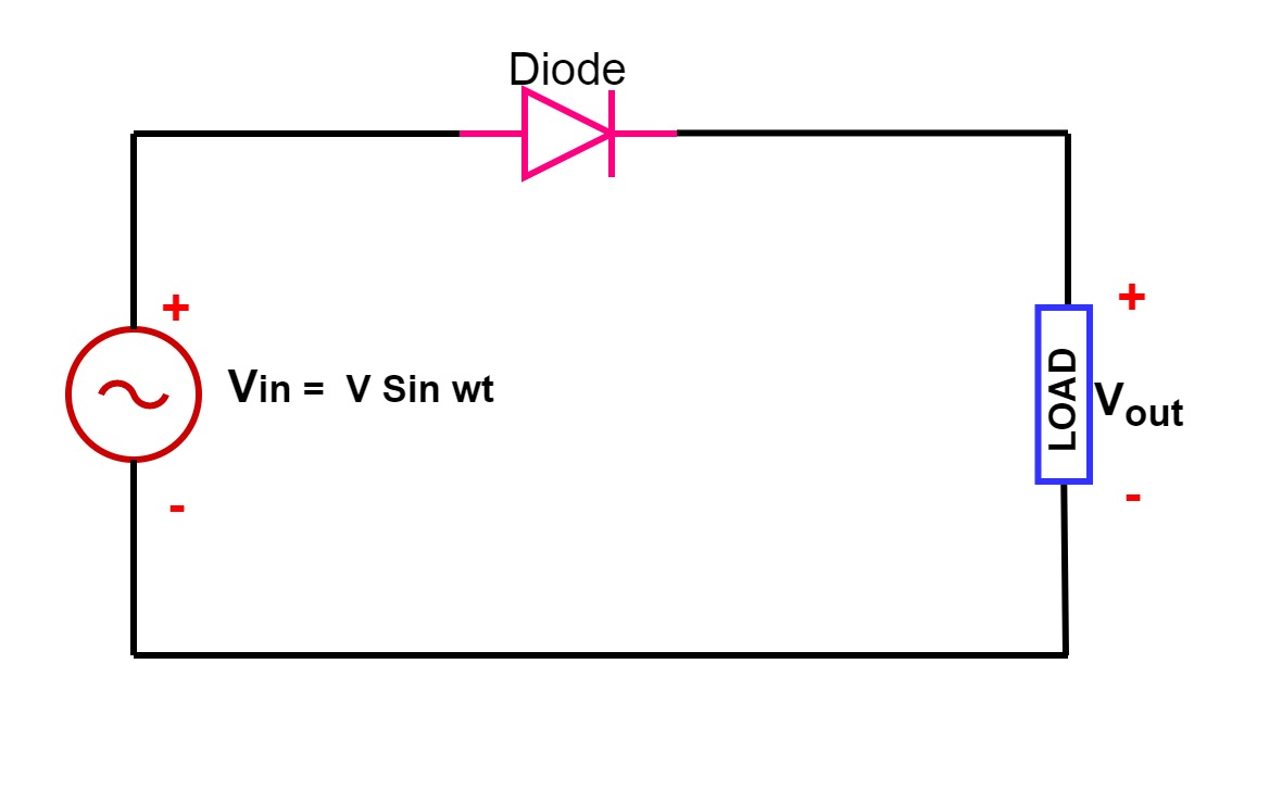
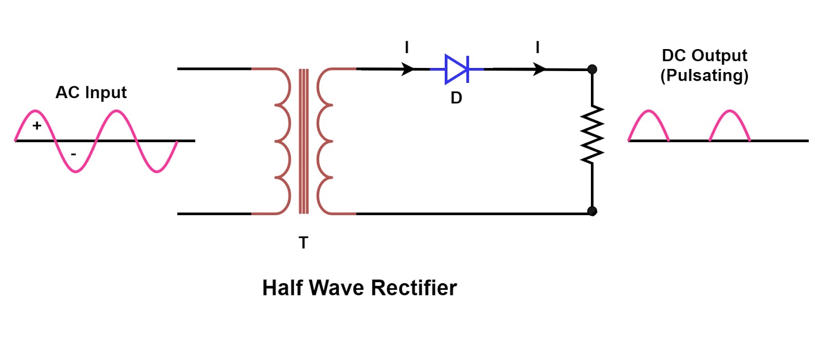
A basic half wave rectifier circuit requires only a diode and a resistor. The diode, acting as the electrical check valve, permits current flow in only one direction. The resistor, placed in series with the diode and the AC source, helps to control the output voltage and current. A common issue with this type of circuit is the significant ripple in the output voltage, resulting in a pulsating DC rather than a smooth, constant voltage. This ripple can be problematic for sensitive electronic components, requiring further filtering stages.
A simple example is a basic battery charger. A half-wave rectifier takes the AC from the wall outlet, allows only the positive half-cycles to pass, and charges the battery with this pulsating DC. While not ideal for all applications, it’s a practical and cost-effective solution for simple charging needs.
One benefit is simplicity: the circuit's minimal component requirement reduces cost and complexity. Another is its low cost, making it attractive for applications where budget is a concern. Finally, it’s easy to understand, serving as an excellent introduction to power electronics concepts.
Advantages and Disadvantages of Half Wave Rectifier Circuits
| Advantages | Disadvantages |
|---|---|
| Simple Design | High Ripple Voltage |
| Low Cost | Low Efficiency |
| Easy to Understand | DC Output is not pure |
Best Practices
1. Diode Selection: Choose a diode with appropriate voltage and current ratings for your application.
2. Filtering: Use a capacitor to smooth the output voltage and reduce ripple.
3. Transformer Usage: For higher voltage applications, use a step-down transformer.
4. Heat Management: Ensure adequate heat dissipation for the diode, especially at higher currents.
5. Safety Precautions: Always work with caution when dealing with AC power.
FAQ:
1. What is a half wave rectifier? A circuit that converts AC to pulsating DC by allowing only one half of the AC cycle to pass.
2. Why is it called half wave? Because it rectifies only half of the input AC wave.
3. What are the main components? A diode and a resistor.
4. What is the output waveform? Pulsating DC.
5. What is ripple voltage? The fluctuating component of the output DC voltage.
6. How can ripple be reduced? By using a filter capacitor.
7. What are the applications? Battery chargers, simple power supplies.
8. What are the limitations? High ripple voltage, low efficiency.
The half-wave rectifier circuit, while simple in its design, plays a crucial role in the world of electronics. It provides a fundamental building block for AC to DC conversion, paving the way for more sophisticated circuits and systems. From its historical roots in early radio to its continued use in modern power supplies, the half-wave rectifier exemplifies how clever design can achieve impactful results with minimal complexity. Understanding its function, benefits, and limitations allows for informed decisions regarding its application and opens the door to exploring more advanced rectifier designs. By mastering the basics of the half-wave rectifier, you equip yourself with valuable knowledge for navigating the fascinating world of power electronics.
Hvac drain pumps conquer condensation chaos
Hourglass timer tattoo meaning deciphering the symbolism on skin
Inkredible puerto rico exploring the islands tattoo scene


