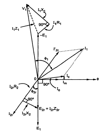
Unlocking Motor Mysteries: The Power of Phasor Diagrams
Ever wondered how engineers visualize the intricate dance of electricity within a motor? The answer lies in the elegant simplicity of the phasor diagram. This graphical tool, a cornerstone of electrical engineering, provides a powerful lens through which we can decipher the complex interplay of voltage, current, and magnetic fields within an electric motor.
Imagine trying to understand the synchronized movements of a complex ballet simply by reading a list of individual steps. It would be nearly impossible! Similarly, grasping the dynamic relationships within a motor requires more than just numerical values. Phasor diagrams offer a visual representation of these relationships, transforming abstract concepts into a readily understandable format. They depict AC quantities as rotating vectors, or "phasors," allowing us to see the phase differences and magnitudes at a glance.
The historical roots of phasor diagrams can be traced back to the development of alternating current (AC) systems in the late 19th century. As engineers grappled with the complexities of AC circuits, the need for a visual aid became apparent. Charles Proteus Steinmetz, a pioneering electrical engineer, is often credited with popularizing the use of phasor diagrams, which became an indispensable tool for analyzing AC circuits, including motors.
The significance of motor phasor diagrams extends far beyond academic curiosity. They are essential for understanding motor performance characteristics, such as power factor, efficiency, and torque. By analyzing the phasor relationships, engineers can identify potential problems, optimize motor design, and troubleshoot issues effectively. These diagrams are a vital tool in a wide range of applications, from designing efficient industrial motors to diagnosing problems in household appliances.
Different types of motors, such as induction motors and synchronous motors, exhibit distinct phasor diagram characteristics. For instance, in an induction motor, the rotor current lags behind the stator current, creating a phase difference that is crucial for producing torque. Understanding these nuances through phasor diagrams is key to effectively working with specific motor types.
A simple example of a phasor diagram application is determining the power factor of a motor. The angle between the voltage and current phasors directly represents the power factor. A smaller angle indicates a higher power factor, which translates to more efficient power utilization.
Benefits of utilizing phasor diagrams include: improved motor design optimization by visualizing the impact of design changes on motor performance, simplified troubleshooting by quickly identifying the root cause of motor issues, and enhanced understanding of motor behavior under various operating conditions.
Creating a phasor diagram involves representing the voltage and current as rotating vectors with their respective magnitudes and phase angles. Specialized software tools and graphical methods are often used to construct these diagrams accurately. Several online resources and textbooks provide step-by-step guidance on constructing and interpreting phasor diagrams for different motor types.
Advantages and Disadvantages of Phasor Diagrams
| Advantages | Disadvantages |
|---|---|
| Visual representation simplifies complex AC relationships | Can be complex for multi-phase systems |
| Facilitates understanding of motor performance parameters | Requires understanding of vector mathematics |
| Aids in troubleshooting and optimization | Static representation doesn't capture dynamic transients |
Frequently Asked Questions about Phasor Diagrams:
1. What is a phasor? A phasor is a rotating vector representing an AC quantity.
2. Why are phasor diagrams useful? They visually represent complex AC relationships in motors.
3. How are they constructed? They are drawn using vector representation of voltage and current with magnitudes and phase angles.
4. What do they reveal about motor performance? They show power factor, efficiency, and other key parameters.
5. How do they aid troubleshooting? They help pinpoint the source of motor problems visually.
6. How do they differ for various motor types? The phase relationships and diagram configuration vary depending on the motor type (induction, synchronous, etc.).
7. Where can I learn more about them? Textbooks on electrical machines and online resources offer in-depth information.
8. What software tools are available for creating them? Several electrical engineering software packages facilitate phasor diagram creation and analysis.
In conclusion, the phasor diagram stands as a testament to the power of visualization in understanding complex electrical systems. From its historical origins to its modern applications, the phasor diagram remains an indispensable tool for anyone working with electric motors. Its ability to simplify complex relationships, facilitate analysis, and aid in problem-solving makes it a cornerstone of electrical engineering. By mastering the art of interpreting these diagrams, we unlock a deeper understanding of motor behavior and pave the way for more efficient and reliable motor designs. Explore the world of phasor diagrams and unleash the power of visual analysis in your electrical engineering endeavors.
The future is now analyzing nfl quarterbacks drafted in the first round over the past five years
Duty honor country the enduring power of gen macarthurs west point farewell
William ellis neff obituaries


