Understanding Phasor Diagrams for Purely Resistive Circuits
Ever wondered how electrical engineers visualize the relationship between voltage and current in AC circuits? That's where phasor diagrams come into play. These visual tools are especially straightforward in purely resistive circuits and provide a clear understanding of how these fundamental components behave.
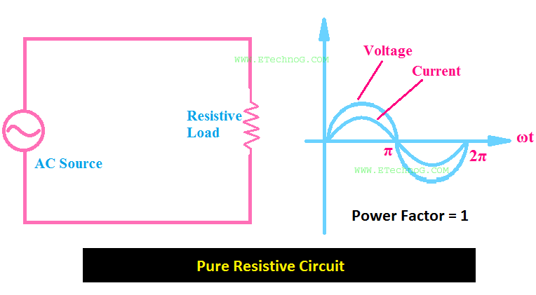
Imagine a simple circuit with just a resistor and an AC voltage source. The voltage and current in this circuit are in perfect sync, rising and falling together. A phasor diagram for this scenario is incredibly simple: both the voltage and current phasors point in the same direction. This illustrates the fundamental characteristic of a purely resistive circuit: there's no phase difference between voltage and current.
Understanding this core concept is key to analyzing more complex AC circuits. Resistive circuits are the building blocks of more elaborate networks, and grasping their behavior is crucial for any budding electrical enthusiast. By visualizing these relationships with phasor diagrams, we gain a clearer insight into how electricity behaves in these fundamental scenarios.
While the concept of phasor diagrams might seem abstract at first, its roots are firmly planted in the practical need to analyze alternating current circuits. Historically, understanding AC behavior was a challenge, and tools like phasor diagrams emerged as powerful aids. These diagrams allowed engineers to represent sinusoidal quantities with vectors, simplifying complex calculations and providing a visual representation of circuit behavior.
The main issue addressed by phasor diagrams in resistive circuits is representing the phase relationship between voltage and current. In a purely resistive circuit, this is trivial, as there's no phase difference. But, as circuits become more complex with the introduction of capacitors and inductors, phasor diagrams become indispensable for visualizing and calculating the phase shifts introduced by these components.
A phasor diagram is simply a vector representation of a sinusoidal quantity, like voltage or current. Its length represents the magnitude, and its angle represents the phase relative to a reference. In a purely resistive circuit, both voltage and current phasors have the same angle, indicating zero phase difference.
For example, consider a resistor of 10 ohms connected to an AC source of 120V. The current flowing through the resistor would be 12A, and the phasor diagram would show both voltage and current phasors aligned along the same axis, reflecting their in-phase relationship.
Benefits of using phasor diagrams in resistive circuits include: simplified representation of AC quantities, easier visualization of phase relationships, and a foundation for understanding more complex AC circuits.
While a phasor diagram for a purely resistive circuit is straightforward, it's a building block for more complex diagrams. Imagine adding a capacitor to the circuit. Now, the current will lead the voltage, and this phase difference is clearly represented in the phasor diagram by an angle between the voltage and current phasors.
Advantages and Disadvantages of Phasor Diagrams
| Advantages | Disadvantages |
|---|---|
| Visualizes phase relationships | Limited to sinusoidal quantities |
| Simplifies AC circuit analysis | Can become complex for large circuits |
Best Practices:
1. Always use a consistent reference phasor.
2. Label all phasors clearly.
3. Choose a suitable scale for the phasor lengths.
4. Indicate the direction of rotation (usually counterclockwise).
5. Keep the diagram clean and uncluttered.
Real-World Examples: Analyzing a simple heating element (purely resistive), modeling the behavior of a filament lamp (approximately resistive), understanding the current flow in a DC circuit (special case with zero frequency), analyzing the power dissipated in a resistor, and calculating the voltage drop across a resistor.
FAQ:
1. What is a phasor? - A vector representing a sinusoidal quantity.
2. Why are phasor diagrams useful? - They simplify AC circuit analysis.
3. What is the phase difference in a purely resistive circuit? - Zero.
4. How do you draw a phasor diagram for a resistor? - Voltage and current phasors are aligned.
5. What is the impedance of a resistor? - Its resistance.
6. How do phasor diagrams relate to complex numbers? - Phasors can be represented using complex numbers.
7. How do you determine the magnitude of a phasor? - It corresponds to the amplitude of the sinusoidal quantity.
8. What is the importance of the angle in a phasor diagram? - It represents the phase shift.
Tips and Tricks: Remember, phasor diagrams are a visual tool. Practice drawing them for various simple circuits. This will help solidify your understanding of AC circuit behavior. Start with simple resistive circuits and gradually introduce other components.
In conclusion, phasor diagrams are essential tools for understanding AC circuit behavior. They provide a clear visual representation of the relationship between voltage and current, especially useful in more complex circuits involving capacitors and inductors. Even in their simplest form, representing purely resistive circuits, phasor diagrams lay the groundwork for more advanced analysis. Mastering this fundamental concept opens doors to understanding more sophisticated electrical systems and empowers you to tackle circuit design and analysis with confidence. Explore further resources and practice creating these diagrams to solidify your grasp of this powerful analytical tool. Start with simple circuits and gradually build your understanding. By embracing phasor diagrams, you gain a powerful ally in your journey through the fascinating world of electrical engineering.
Unmasking the past who was william henry scott
Imagenes de caratula de lengua y literatura unveiling the power of visuals in language and literature
Unlock your fishing potential garmin echomap uhd2 54cv review


