Decoding the SPDT Switch Symbol: A Circuitry Essential
Ever peered at a circuit diagram and felt a flicker of confusion at those cryptic symbols? You're not alone! Understanding the visual language of electronics is crucial, and today we're tackling a fundamental component: the Single-Pole Double-Throw (SPDT) switch. Specifically, we're diving deep into the graphical representation – the SPDT switch symbol – that unlocks its function within a circuit.
The SPDT switch symbol, a small but mighty glyph, holds the key to understanding how this versatile switch routes electrical flow. Imagine it as a tiny railroad switch, directing the current down different tracks. This seemingly simple representation packs a punch, allowing engineers and hobbyists alike to design and troubleshoot circuits efficiently. Mastering the SPDT switch symbol is like learning a secret handshake in the world of electronics.
Why is understanding this symbol so important? In the intricate dance of electrons, precision is paramount. Misinterpreting the SPDT switch diagram can lead to faulty circuits, malfunctioning devices, or even safety hazards. A clear understanding of the symbol ensures you're wiring things correctly, whether you're building a simple circuit or a complex electronic system.
The evolution of the SPDT switch symbol is intertwined with the history of electrical engineering itself. From early schematic drawings to standardized representations, the symbol has evolved to become a universally recognized language. This visual shorthand allows engineers across the globe to communicate complex circuit designs seamlessly. It's a testament to the power of visual communication in a highly technical field.
While there isn't a definitive "origin story" for the specific SPDT switch symbol, its design likely emerged from a need for clarity and simplicity. Early electrical diagrams were often messy and confusing, leading to errors and misunderstandings. The standardized symbol emerged as a solution, providing a clear and concise way to represent the switch's function. This standardization is critical for ensuring that circuits are built and understood correctly, regardless of who designed them.
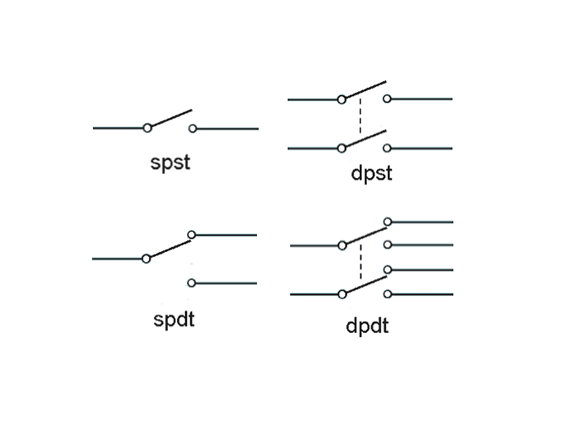
The SPDT switch symbol typically depicts a single input line connecting to a "pole" (the common connection). From this pole, two lines branch out, representing the two "throws" or output connections. This visual representation clearly shows how the switch directs current flow from the common pole to one of the two output throws. A simple example is a lamp controlled by two separate switches: the SPDT switch allows either switch to turn the lamp on or off.
One significant benefit of understanding SPDT switch diagrams is the ability to easily troubleshoot circuits. By tracing the symbol's connections on a diagram, you can identify potential problems and quickly isolate faulty components. Another advantage is the ability to design and modify circuits with confidence. With a clear understanding of the symbol, you can incorporate SPDT switches into your designs effectively, enabling complex functionalities.
A step-by-step guide to interpreting an SPDT switch schematic involves identifying the common terminal (pole) and the two output terminals (throws). Then, trace the connections to understand how the switch routes the current in different positions. Observing the switch's physical position can then be correlated to the diagram to determine the current flow path.
Advantages and Disadvantages
| Advantages | Disadvantages |
|---|---|
| Versatility in circuit design | Slightly more complex than SPST switches |
| Enables multiple control points | Can be confusing for beginners |
Frequently Asked Questions:
1. What does SPDT stand for? Single-Pole Double-Throw.
2. How many connections does an SPDT switch have? Three.
3. Can an SPDT switch be used as an on/off switch? Yes, by leaving one throw unconnected.
4. What's the difference between SPDT and DPDT? SPDT has one input, DPDT has two.
5. Where can I find SPDT switches? Electronics stores, online retailers.
6. How do I wire an SPDT switch? Refer to a wiring diagram specific to your application.
7. What are some common applications of SPDT switches? Selecting between two audio sources, reversing motor direction.
8. Are there different types of SPDT switch symbols? While the basic form is standardized, variations can exist in specific diagrams.
One tip for working with SPDT switch representation is to always double-check your connections against the diagram to ensure accurate wiring. This helps prevent errors and ensures your circuit functions as intended. Another trick is to use a multimeter to verify the continuity between the terminals in different switch positions, confirming your understanding of the symbol and the switch's behavior.
In conclusion, the seemingly simple SPDT switch symbol is a powerful tool in the world of electronics. Understanding its meaning and application unlocks a world of circuit design possibilities. From controlling simple lamps to complex industrial systems, the SPDT switch plays a vital role. Mastering this symbol empowers you to confidently navigate circuit diagrams, troubleshoot problems, and design innovative electronic solutions. By recognizing its importance and familiarizing yourself with its variations, you gain a crucial skill in the exciting realm of electronics. So, dive in, explore the world of SPDT switches and their symbolic language, and unlock your potential as a circuit wizard! Remember, this small symbol represents a big step towards understanding the fascinating world of electronics. Continue to explore, learn, and experiment – the possibilities are endless!
Unlocking the magic of sweet bluette a benjamin moore masterpiece
Navigating early pregnancy leave in indonesia permohonan balik awal mengandung
Decoding the matrix of sherwin williams white paint


