Decoding the Normally Closed Contactor Symbol: Electrical Control Essentials
Imagine a gate that's usually shut, only swinging open when given a specific command. That, in essence, is the function of a normally closed (NC) contact within a contactor. This seemingly simple symbol represents a crucial element in electrical control systems, governing the flow of power and enabling automation in countless applications.
Understanding the normally closed contactor symbol is fundamental for anyone working with electrical circuits, from electricians and engineers to technicians and hobbyists. This article demystifies the NC contact, exploring its significance in controlling electrical loads and ensuring safe operation.
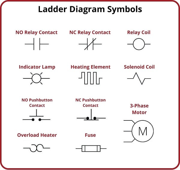
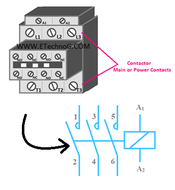
The normally closed contact symbol typically appears as two parallel lines, one slightly curved to indicate its spring-loaded nature, connected to a control circuit. This symbol represents a conductive path that's closed by default. When the contactor coil energizes, it creates a magnetic field that pulls the NC contact open, interrupting the flow of current through the circuit.
This "break-before-make" action is what differentiates the NC contact from its normally open counterpart. This distinction is vital in designing safety circuits, emergency stops, and various control applications where a default "off" state is required.
The history of the normally closed contact symbol is intertwined with the development of electrical control systems themselves. As industries embraced automation, the need arose for reliable switching mechanisms. Contactors, with their ability to handle high currents and integrate into complex control logic, became essential components. The standardized symbols, including the NC contact representation, emerged to facilitate clear communication and efficient circuit design.
A simple example of a normally closed contact application is a safety circuit for a motor. The NC contact is placed in series with the motor's power supply. Under normal conditions, the contact is closed, allowing the motor to run. However, if a safety sensor detects an issue, like an obstruction or open guard, it de-energizes the contactor coil. This opens the NC contact, cutting off power to the motor and preventing potential harm.
One key benefit of utilizing normally closed contacts is enhanced safety. By defaulting to an "off" state, they provide a fail-safe mechanism. If the control circuit experiences a power loss or malfunction, the NC contact will open, preventing unintended operation of the controlled device.
Another advantage is simplified control logic. In certain applications, using normally closed contacts can streamline the design of the control circuit, requiring fewer components and reducing complexity.
Furthermore, normally closed contacts offer energy efficiency. In applications where a device needs to be deactivated for extended periods, the normally closed configuration prevents continuous power consumption by default.
Advantages and Disadvantages of Normally Closed Contactor Symbols
| Advantages | Disadvantages |
|---|---|
| Enhanced Safety (Fail-Safe) | Can be counterintuitive in some circuit designs |
| Simplified Control Logic | Requires careful consideration of power flow in fault conditions |
| Energy Efficiency | May increase component count in specific scenarios |
Best Practices for Implementing Normally Closed Contactor Symbols:
1. Clearly label all NC contacts on circuit diagrams to avoid confusion.
2. Verify the correct voltage and current ratings of the contactor for the intended application.
3. Consider potential failure modes and ensure the NC contact configuration provides the desired safety behavior.
4. Regularly inspect and maintain contactors to ensure reliable operation.
5. Consult relevant electrical codes and standards for specific application requirements.
Frequently Asked Questions:
1. What is the difference between a normally closed and a normally open contact? A normally closed contact is closed in its default state, while a normally open contact is open in its default state.
2. How is a normally closed contact represented in a circuit diagram? It is represented by two parallel lines, one slightly curved, connected to the control circuit.
3. What happens when a contactor coil is energized with a normally closed contact? The NC contact opens, interrupting the circuit.
4. What are some common applications of normally closed contacts? Safety circuits, emergency stops, and control systems requiring a default "off" state.
5. What are the benefits of using normally closed contacts? Enhanced safety, simplified control logic, and energy efficiency.
6. What considerations should be taken when implementing normally closed contacts? Voltage and current ratings, failure modes, and adherence to electrical codes.
7. How are normally closed contacts different from relays? Contactors typically handle higher currents than relays.
8. Where can I find more information on contactor symbols? Textbooks on electrical control systems and online resources.
Tips and tricks: When troubleshooting circuits with NC contacts, remember their default state. A multimeter can be used to check the continuity of the contact in both energized and de-energized states.
In conclusion, the normally closed contactor symbol represents a fundamental building block in electrical control systems. Its ability to interrupt power flow in a predictable manner is crucial for safety, efficient operation, and automation across numerous industries. Understanding the symbol, its function, and best practices for implementation is essential for anyone working with electrical circuits. By mastering the nuances of the normally closed contact, engineers and technicians can design and maintain reliable and safe control systems, powering the modern world. Further exploration of contactor technology and control circuit design can be found in specialized textbooks and online resources, empowering individuals to delve deeper into this fascinating field.
Banish hard water spots restore your cars sparkling finish
Effortless buoyancy the undeniable chic of water safety
Exploring sherwin williams paint colors with google tools


