Decoding Residential Electrical Blueprints: The Power of Symbols
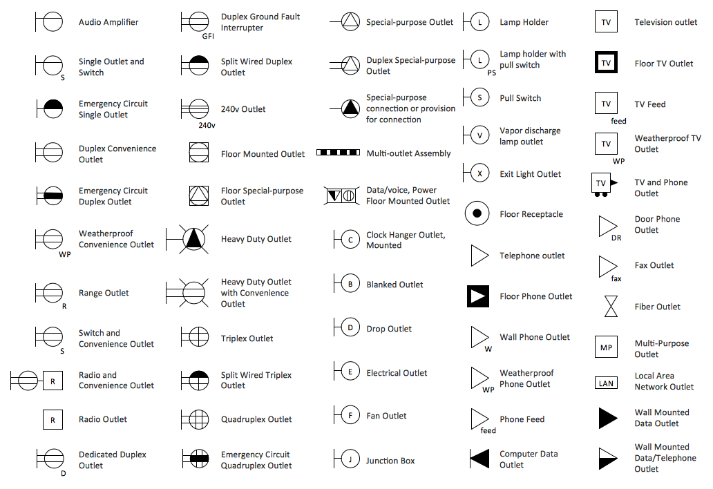
Ever wonder what those cryptic squiggles and circles on your house blueprint represent? They're not just abstract art – they're the language of electricity, and they hold the key to powering your dream home. Understanding electrical symbols in residential plans is crucial for everyone involved in a building project, from homeowners to contractors and electricians. These symbols are the roadmap for wiring your home, ensuring safety, and avoiding costly rework.
Residential electrical drawings, packed with specialized symbols, depict the electrical system's layout within a home. These representations dictate everything from the placement of outlets and switches to the routing of wires and the location of major electrical components. Imagine trying to build a complex structure without a blueprint. Similarly, electrical diagrams using standardized symbols provide a precise guide for electricians, preventing misinterpretations and ensuring a functional and safe electrical system.
The use of standardized electrical symbols in residential plans evolved over time, driven by the need for clear communication and safety in the construction industry. Early electrical systems were simpler, but as technology advanced, the need for a universal language became apparent. Organizations like the National Electrical Contractors Association (NECA) and the American National Standards Institute (ANSI) played a vital role in standardizing these symbols, ensuring consistency across projects and regions. This standardization minimizes errors, improves efficiency, and promotes safety on construction sites.
These standardized symbols are critical for avoiding potential hazards, such as overloaded circuits, improperly grounded appliances, and fire risks. Inaccurate or unclear electrical plans can lead to costly rework, delays in construction, and even dangerous electrical malfunctions after the house is occupied. Clear diagrams, utilizing the correct depictions for outlets, switches, fixtures, and circuit breakers, are essential for preventing these problems.
Without a shared vocabulary of symbols, electricians would be forced to rely on lengthy written descriptions, which are prone to misinterpretations. Visual representations are far more efficient and less ambiguous, allowing electricians to quickly grasp the intended layout and wiring configuration. This efficiency translates into faster installation times, reduced labor costs, and a smoother construction process overall. From a simple switch symbol to the complex representation of a three-way switch, each graphic element conveys a specific piece of information, ensuring everyone is on the same page.
Understanding basic electrical drawing representations is like learning a new language. A straight line represents a wire, a circle with a cross inside signifies a ceiling light, and a rectangle with two diagonal lines indicates a duplex receptacle. These seemingly simple symbols convey essential information about the electrical system's layout and functionality. For example, knowing the difference between a single-pole switch symbol and a three-way switch symbol is essential for proper installation and operation.
Benefits of standardized electrical symbols include improved communication, increased efficiency, and enhanced safety. Clear communication minimizes errors and ensures that everyone involved in the project understands the electrical plan. Increased efficiency leads to faster installation and reduced labor costs. Enhanced safety reduces the risk of electrical hazards and ensures a safe and functional electrical system.
Advantages and Disadvantages of Standardized Electrical Symbols
| Advantages | Disadvantages |
|---|---|
| Clear Communication | Requires Training to Understand |
| Improved Efficiency | Potential for Misinterpretation if not used correctly |
| Enhanced Safety | Constant updates and revisions may occur |
Best Practices: 1. Use the latest ANSI/IEEE standard symbols. 2. Clearly label all symbols. 3. Maintain consistency throughout the plan. 4. Use a legend to explain any non-standard symbols. 5. Ensure the plan is reviewed by a qualified electrician.
Real Examples: 1. A lighting plan for a kitchen. 2. A power plan for a living room. 3. A wiring diagram for a home theater system. 4. An electrical schematic for a smart home. 5. A site plan showing the location of the electrical service entrance.
FAQ: 1. What does a circle with a dot in the center represent? (A ceiling-mounted light fixture) 2. What does a rectangle with two diagonal lines signify? (A duplex receptacle/outlet) 3. What is the symbol for a GFCI outlet? (A circle with the letters "GFCI" inside) 4. What does a dashed line represent? (A concealed wire) 5. What is the symbol for a three-way switch? (Two switches connected by a dashed line) 6. What does the letter "S" within a circle represent? (A single-pole switch) 7. What do the letters "GF" within a circle indicate? (A ground fault circuit interrupter breaker) 8. What is a home run on an electrical plan? (The main wire running from the electrical panel to the first device on the circuit)
Tips & Tricks: Use software designed for creating electrical diagrams, consult with experienced electricians, and regularly review updated symbol standards.
In conclusion, electrical symbols for residential plans are essential for clear communication, efficient construction, and, most importantly, safety. Understanding these symbols empowers homeowners, contractors, and electricians to work together seamlessly, ensuring a properly functioning and safe electrical system. These visual representations prevent costly mistakes, ensure code compliance, and ultimately contribute to the successful completion of any residential building project. By mastering the language of electrical symbols, we pave the way for a brighter, safer, and more efficient future for our homes. Take the time to familiarize yourself with these crucial symbols; it's an investment in the safety and functionality of your home. Whether you're building a new home or renovating an existing one, understanding the language of electricity is key to powering your vision and bringing your dream home to life.
Navigating the brunswick power grid landscape
747 horsepower unveiling the power of the queen of the skies
Wells fargo 401k lawsuit what you need to know


