Decoding Circuitry Electronic Symbol Diagrams Explained
Ever stared at a circuit diagram and felt like you were deciphering an alien language? Those enigmatic squiggles and shapes aren't random doodles; they're the language of electronics, communicated through standardized electronic symbols. Understanding these symbols is the key to unlocking the secrets of circuitry, whether you're a seasoned engineer or a curious beginner.
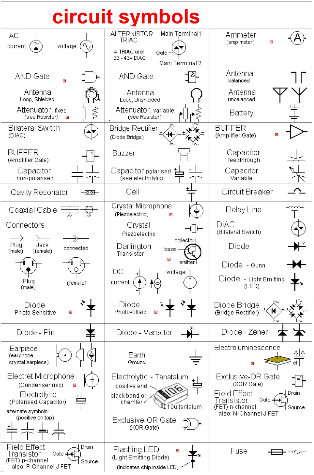
An electronic symbols chart, labeled in English, provides a visual vocabulary for electronic components. This standardized system allows engineers and hobbyists worldwide to communicate circuit designs clearly and concisely. Imagine trying to describe a complex circuit using only words – it would be a chaotic mess. These labeled diagrams provide a universal language, making collaboration and innovation possible.
The history of electronic symbols is intertwined with the development of electronics itself. As circuits became more complex, the need for a standardized visual representation became crucial. Early diagrams were often crude and varied, but over time, organizations like the IEEE (Institute of Electrical and Electronics Engineers) and IEC (International Electrotechnical Commission) developed standardized symbol sets. These labeled charts, available in English and other languages, are essential tools for anyone working with electronics.
The importance of standardized electronic symbol representation can't be overstated. These diagrams are the blueprints for every electronic device we use, from smartphones to spacecraft. They enable engineers to design, analyze, and troubleshoot circuits efficiently. Without a common visual language, the world of electronics would be a fragmented landscape of incompatible designs.
One of the main issues surrounding electronic symbols is keeping up with the rapid pace of technological advancement. As new components are developed, new symbols need to be created and standardized. This requires ongoing collaboration and communication within the electronics community to ensure clarity and consistency across different diagrams and labeled electronic symbol charts.
A resistor, represented by a zig-zag line, restricts the flow of current. A capacitor, depicted by two parallel lines, stores electrical energy. A transistor, shown as a triangle with a line attached, amplifies or switches electronic signals. These are just a few examples from a comprehensive electronic symbols chart labeled in English.
Benefits of using standardized, labeled diagrams include improved communication, efficient troubleshooting, and easier collaboration. For instance, an engineer in the US can easily understand a circuit diagram created by an engineer in Japan, thanks to the standardized symbols. This facilitates international collaboration and accelerates innovation.
If you're starting with electronics, a good action plan is to familiarize yourself with a basic electronic symbols chart labeled in English. Start with common components like resistors, capacitors, and transistors. Practice reading simple circuit diagrams and try building basic circuits. Numerous online resources and textbooks offer tutorials and practice exercises.
Advantages and Disadvantages of Standardized Electronic Symbols
| Advantages | Disadvantages |
|---|---|
| Clear communication | Requires learning and memorization |
| Efficient troubleshooting | Can become complex for highly integrated circuits |
| International collaboration | Constant updates required with new technology |
Best practices include using clear and concise labels, adhering to standardized symbols, and organizing diagrams logically. For example, always label components with their values and ensure signal flow is easy to follow.
Frequently Asked Questions:
1. Where can I find a comprehensive electronic symbols chart? - Search online for "electronic symbols chart labeled in English."
2. Are there different standards for electronic symbols? - Yes, but the IEEE and IEC standards are widely adopted.
3. What is the symbol for a diode? - A triangle with a line at one vertex.
4. How can I learn to read circuit diagrams? - Start with basic tutorials and gradually progress to more complex circuits.
5. Are there software tools for creating electronic diagrams? - Yes, numerous software packages are available.
6. Why is it important to use standardized symbols? - For clear communication and collaboration.
7. How often are new symbols added? - As new components are developed.
8. Can I create my own electronic symbols? - It's best to adhere to established standards.
Tips and tricks for working with electronic symbol diagrams include using color-coding to highlight different sections of a circuit and using hierarchical design techniques for complex systems.
In conclusion, understanding electronic symbols is fundamental to anyone working with or interested in electronics. Labeled electronic symbol charts, particularly those in English, provide a crucial visual language for describing and analyzing circuits. From designing complex systems to troubleshooting simple circuits, these diagrams are essential tools. The ability to interpret and utilize these symbols empowers you to navigate the intricate world of electronics, fostering innovation and collaboration on a global scale. By mastering this language of circuits, you unlock the power to design, build, and repair the technology that shapes our modern world. So, grab an electronic symbols chart, start learning, and begin exploring the fascinating world of circuitry. The future of technology depends on those who can speak its language.
Unlocking young minds the magic of math crossword puzzles for year 1
Espn mock draft frenzy your fantasy football domination starts now
Boost your browsing mastering microsoft edge font size


.jpg)


