Decoding Circuit Secrets: Your Guide to Electrical Schematics
Ever wondered how electricians and engineers communicate the intricate details of electrical systems? The secret lies in a universal language of symbols: electrical schematic symbols. These symbols, often compiled in handy PDF documents, are the key to understanding and building everything from simple circuits to complex power grids. Think of them as the words in a sentence, each conveying a specific meaning, combining to tell the complete story of an electrical system.
Navigating the world of electronics can feel daunting, especially for beginners. But with the right tools and knowledge, understanding electrical drawings becomes an empowering skill. This comprehensive guide will delve into the world of electrical schematic symbols PDF, exploring their history, importance, and practical applications. Whether you're a hobbyist, student, or professional, you'll discover valuable insights into interpreting these essential diagrams.
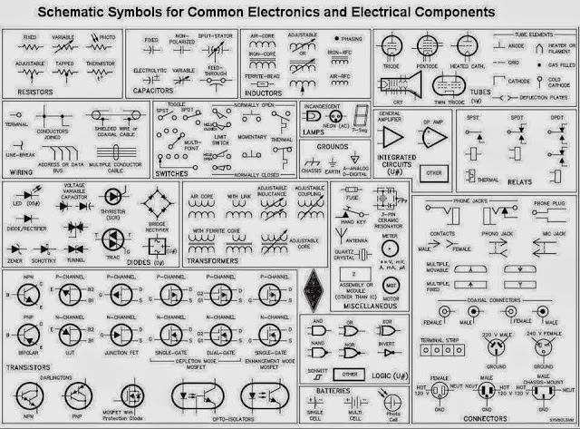
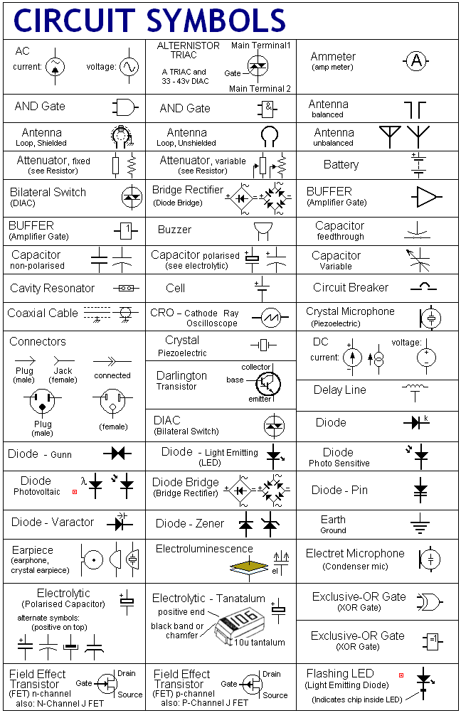
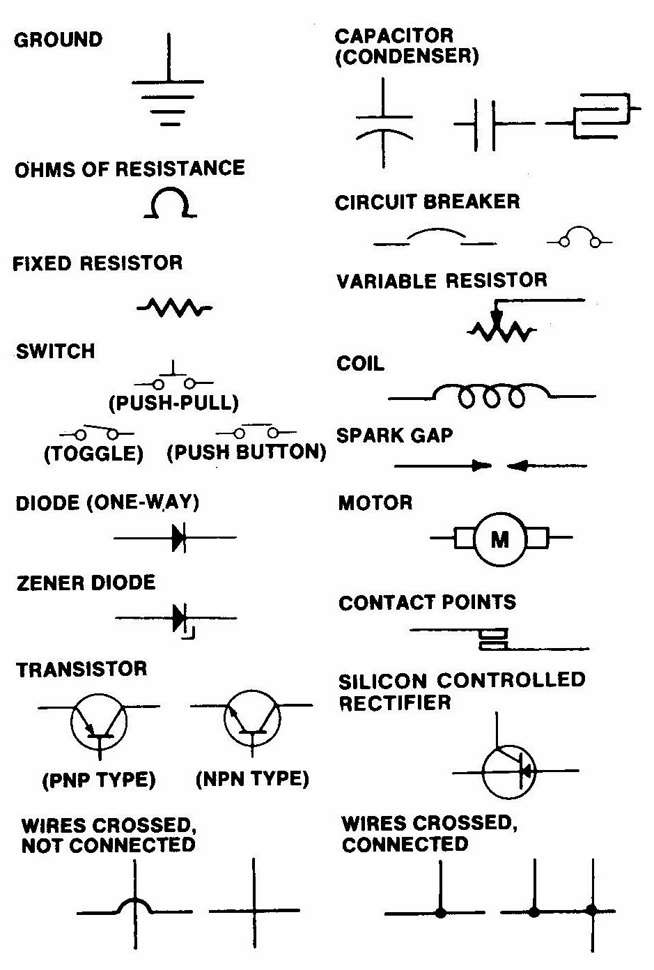
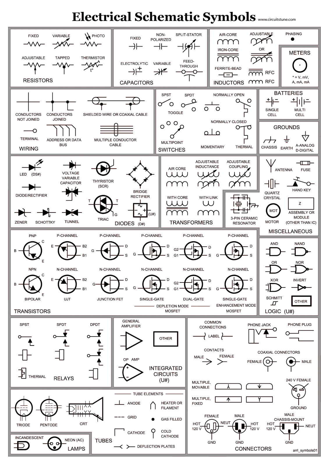
Electrical schematic symbols are graphical representations of electrical and electronic components. These standardized symbols ensure clear and concise communication among professionals worldwide. Think of a resistor symbol, a zigzag line, universally recognized as a component that resists the flow of current. Accessing these symbols in a portable and printable PDF format is incredibly valuable, allowing for quick reference and sharing.
The history of electrical schematic symbols is intertwined with the development of electricity itself. As electrical systems became more complex, the need for a standardized visual language emerged. Early diagrams evolved over time, eventually leading to the internationally recognized symbols we use today. Finding downloadable electrical schematic symbols PDF resources provides a direct link to this historical evolution and allows anyone to learn this crucial language.
The importance of electrical schematic symbols cannot be overstated. They provide a blueprint for building and troubleshooting electrical circuits, ensuring safety and efficiency. Imagine trying to assemble a complex piece of furniture without instructions – electrical schematics provide the necessary instructions for electrical systems. Having a reliable electrical schematic symbols PDF at your fingertips is like having a trusted guide, helping you navigate the complexities of circuits with confidence.
Electrical schematic diagrams use symbols to represent various components like resistors, capacitors, transistors, switches, and power sources. For instance, a battery is represented by two parallel lines, one longer than the other, indicating the positive and negative terminals. A simple example is a circuit diagram showing a battery connected to a lamp via a switch. The schematic uses symbols for each component, clearly illustrating how they are interconnected.
One benefit of using standardized electrical schematic symbols is clarity. Imagine trying to decipher a circuit diagram using different symbols for the same component - it would be chaotic. Standardization ensures everyone understands the diagram regardless of their background. Another benefit is efficiency. Using symbols saves space and time compared to lengthy written descriptions, making it easier to design, analyze, and troubleshoot circuits. Finally, safety is paramount in electrical work. Accurate schematic diagrams with clear symbols minimize the risk of errors and ensure safe installation and maintenance of electrical systems.
To effectively use electrical schematic symbols, familiarize yourself with common symbols using resources like an electrical schematic symbols PDF. Practice reading and interpreting simple circuit diagrams and gradually progress to more complex ones. Utilizing online circuit simulators can also provide hands-on experience.
Advantages and Disadvantages of Using PDF Schematics
| Advantages | Disadvantages |
|---|---|
| Portability and easy sharing | Difficult to edit directly |
| Printable and readily available | Static format, less interactive than online tools |
| Can be viewed on various devices | Potential compatibility issues with older software |
Best practices for working with electrical schematics include maintaining consistent symbol usage, clearly labeling all components and connections, and regularly updating diagrams as needed. Ensuring proper documentation and version control is crucial for collaborative projects. Always double-check your work and seek expert advice when dealing with complex or unfamiliar circuits.
Challenges in working with electrical schematics can include interpreting complex diagrams, keeping up with evolving standards, and managing large-scale projects. Solutions involve utilizing specialized software, collaborating with experienced professionals, and implementing robust version control systems.
FAQs include questions about finding reliable schematic symbols PDF resources, understanding specific symbols, and troubleshooting common circuit problems. Answers can be found in online tutorials, reference books, and forums.
In conclusion, understanding and utilizing electrical schematic symbols is fundamental to working with electrical systems. These symbols, often accessible through handy electrical schematic symbols PDF documents, provide a clear and efficient language for communicating complex circuit designs. From basic circuits to intricate systems, mastering this symbolic language empowers you to design, build, and troubleshoot electrical projects with confidence and safety. Embrace the power of these symbols, and you'll unlock a world of electrical possibilities. Explore resources like online libraries and forums, and never stop learning. The world of electrical schematics is constantly evolving, and continuous learning is key to staying ahead.
Finding solace a guide to funeral homes in willoughby hills ohio
Red label tea price in karnataka your comprehensive guide
Rediscovering romance the allure of marry my husband flower manga


.jpg)