Decoding Circuit Diagrams Electronic Component Symbols Made Easy
Ever stared at a circuit diagram and felt like you were deciphering hieroglyphics? Don't worry, you're not alone. Understanding electronic component symbols is the key to unlocking the world of electronics, and it's easier than you think. This comprehensive guide will equip you with the knowledge to confidently navigate the visual language of circuits.
Electronic component symbols are standardized representations of physical components used in electronic circuits. These graphic representations are crucial for designing, analyzing, and troubleshooting circuits. Imagine trying to build a complex electronic system without a common visual language – it would be chaos. These symbols provide a universal shorthand that engineers and hobbyists alike use to communicate circuit designs clearly and efficiently.
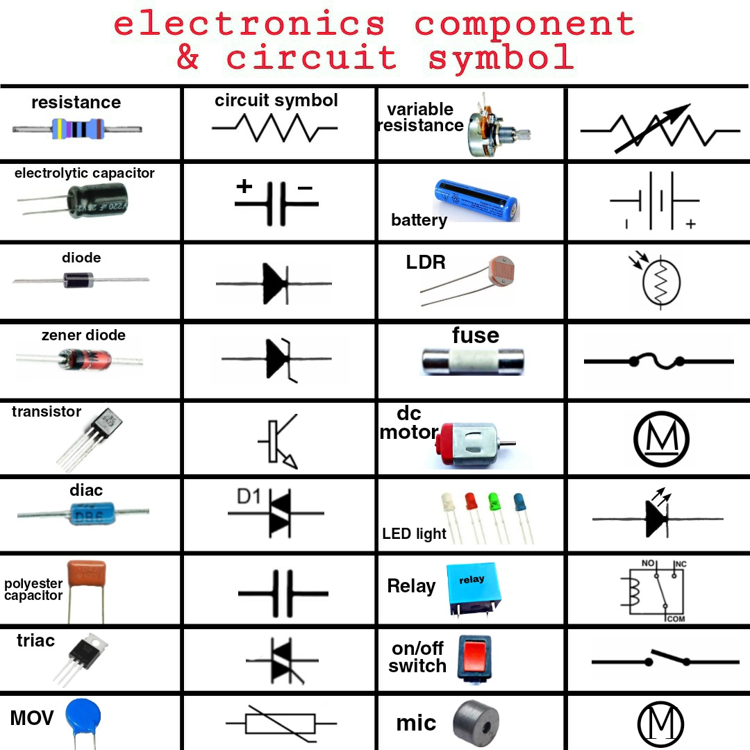
From the simple resistor to the complex integrated circuit, each component has its own unique symbol. These symbols often provide clues to the component's function. For instance, the resistor symbol, a zigzag line, represents the resistance to current flow. The capacitor symbol, two parallel lines, visually represents the two plates that store electrical charge. This visual language significantly simplifies complex designs, allowing engineers to quickly grasp the functionality of a circuit at a glance.
The history of electronic component symbols is intertwined with the development of electronics itself. As electronic circuits became more complex, the need for a standardized system of representation became apparent. Early symbols often resembled the physical component they represented. Over time, these symbols evolved into more abstract forms, optimized for clarity and ease of drawing. This evolution has resulted in the internationally recognized standards we use today.
Understanding these symbols is fundamental for anyone working with electronics. Whether you're a seasoned engineer designing complex systems or a beginner just starting out with basic circuits, a solid grasp of component symbols is essential. This knowledge empowers you to read and interpret circuit diagrams, troubleshoot malfunctioning electronics, and even design your own circuits. It's like learning the alphabet of electronics, opening up a world of possibilities.
The importance of standardized symbols cannot be overstated. They prevent miscommunication and errors in circuit design, manufacturing, and maintenance. Imagine the potential consequences if different engineers interpreted the same symbol differently. Standardized symbols ensure everyone is on the same page, fostering collaboration and preventing costly mistakes.
One common issue with electronic component symbols is the existence of multiple standards, particularly between American and European systems. However, the core symbols remain largely consistent, and with a little practice, navigating these minor differences becomes second nature. Recognizing these variations can help avoid confusion when working with diagrams from different regions.
One of the biggest benefits of using standardized electronic component symbols is enhanced communication. These symbols create a common language for anyone working with electronics, allowing for clear and concise communication of circuit designs.
Another benefit is improved design efficiency. By using symbols, engineers can quickly and easily sketch out circuit diagrams without having to draw detailed representations of each component, saving valuable time and effort.
Troubleshooting circuits becomes much easier with a clear understanding of component symbols. By examining the diagram, technicians can quickly identify potentially faulty components, streamlining the repair process.
If you're new to electronics, start by learning the symbols for the most common components, such as resistors, capacitors, and diodes. Several online resources and textbooks provide comprehensive lists of electronic component symbols.
Advantages and Disadvantages of Standardized Electronic Component Symbols
| Advantages | Disadvantages |
|---|---|
| Clear communication | Minor variations between standards can cause confusion. |
| Improved design efficiency | Requires initial learning and memorization. |
| Simplified troubleshooting |
Best Practice 1: Always refer to a reliable source for symbols, especially when encountering unfamiliar components.
Best Practice 2: Ensure consistency in symbol usage throughout a single diagram.
Best Practice 3: Clearly label all components with their values and designations.
Best Practice 4: Use a consistent orientation for symbols to improve readability.
Best Practice 5: Maintain a neat and organized diagram to avoid confusion.
FAQ 1: Where can I find a comprehensive list of electronic component symbols? Many online resources and textbooks provide such lists. A simple web search will yield numerous results.
FAQ 2: What's the difference between American and European symbols? While there are some variations, the core symbols are largely consistent.
FAQ 3: How can I learn these symbols quickly? Start with the most common components and practice drawing simple circuits.
FAQ 4: Why are standardized symbols important? They ensure clear communication and prevent errors in circuit design.
FAQ 5: Are there any software tools for drawing circuit diagrams? Yes, many software packages are available, ranging from free online tools to professional-grade applications.
FAQ 6: What is the symbol for a diode? A triangle with a line across one end.
FAQ 7: What is the symbol for a transistor? A symbol with three leads, resembling a small arrow.
FAQ 8: What is the symbol for a resistor? A zigzag line.
Tip: Create flashcards to help memorize component symbols. Trick: Relate symbols to their component's function to aid memorization.
In conclusion, understanding basic electronic component symbols is fundamental to navigating the world of electronics. From simplifying complex circuit designs to enabling effective troubleshooting, these symbols serve as the essential building blocks of electronic communication. Mastering these visual representations unlocks the ability to design, analyze, and repair electronic circuits efficiently. By familiarizing yourself with the common symbols and adhering to best practices, you can confidently delve into the fascinating realm of electronics. Take advantage of the numerous online resources, practice regularly, and soon you'll be fluent in the language of circuits. This knowledge empowers you to engage with electronics on a deeper level, opening up a world of innovation and problem-solving. So, embrace the challenge and embark on your journey to mastering electronic component symbols – you won't regret it!
Jenama telefon bimbit di malaysia a journey through time
The allure of spider and rose tattoos a symbolism deep dive
Revive your rugs the ultimate guide to restoring matted carpet


.jpg)


