Conquer AC Circuits: Unleash the Power of Phasor Analysis
Ever feel like alternating current (AC) circuits are a confusing maze of sines and cosines? Ready to ditch the tedious trigonometry and conquer these circuits with a streamlined approach? Phasor analysis is your secret weapon. It's the smart, efficient way to analyze AC circuits, transforming complex differential equations into simpler algebraic ones. Think of it as a financial shortcut – optimizing your effort to achieve maximum results, but with circuits instead of dollars.
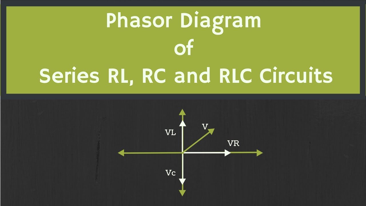
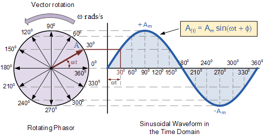
Phasor analysis is a powerful technique used to analyze the steady-state behavior of AC circuits. It simplifies calculations by representing sinusoidal voltages and currents as rotating vectors, known as phasors. These phasors encapsulate both the magnitude and phase of the sinusoidal quantity, allowing us to analyze circuits in the frequency domain rather than wrestling with time-domain differential equations. This method provides a much more manageable and intuitive approach to understanding complex circuit behavior.
This ingenious method emerged from the need to simplify the analysis of AC circuits, particularly those operating at a single frequency. Charles Proteus Steinmetz, a brilliant electrical engineer, is credited with pioneering the use of phasors in the late 19th century. Before phasor analysis, analyzing AC circuits involved solving intricate differential equations, a time-consuming and error-prone process. Phasors revolutionized circuit analysis, making it accessible and practical for a wider range of engineers. Today, it's an essential tool in electrical engineering, powering the design and analysis of everything from power systems to electronic devices.
One of the main issues addressed by the phasor method is the difficulty in handling sinusoidal functions in circuit calculations. Directly manipulating trigonometric functions can be cumbersome, especially when dealing with multiple sources and complex impedances. Phasor analysis tackles this challenge by transforming the time-domain sinusoidal functions into the frequency domain, represented by phasors. This transformation simplifies calculations significantly, allowing us to use basic algebraic techniques instead of complex calculus.
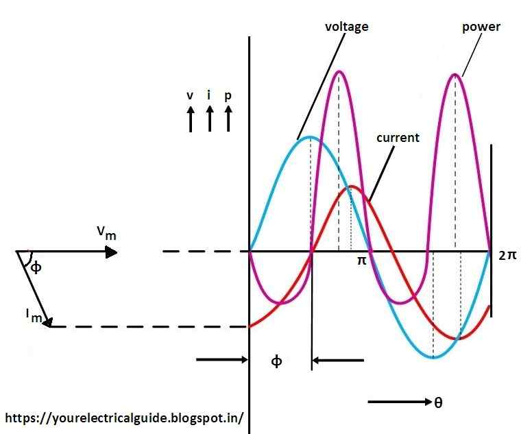
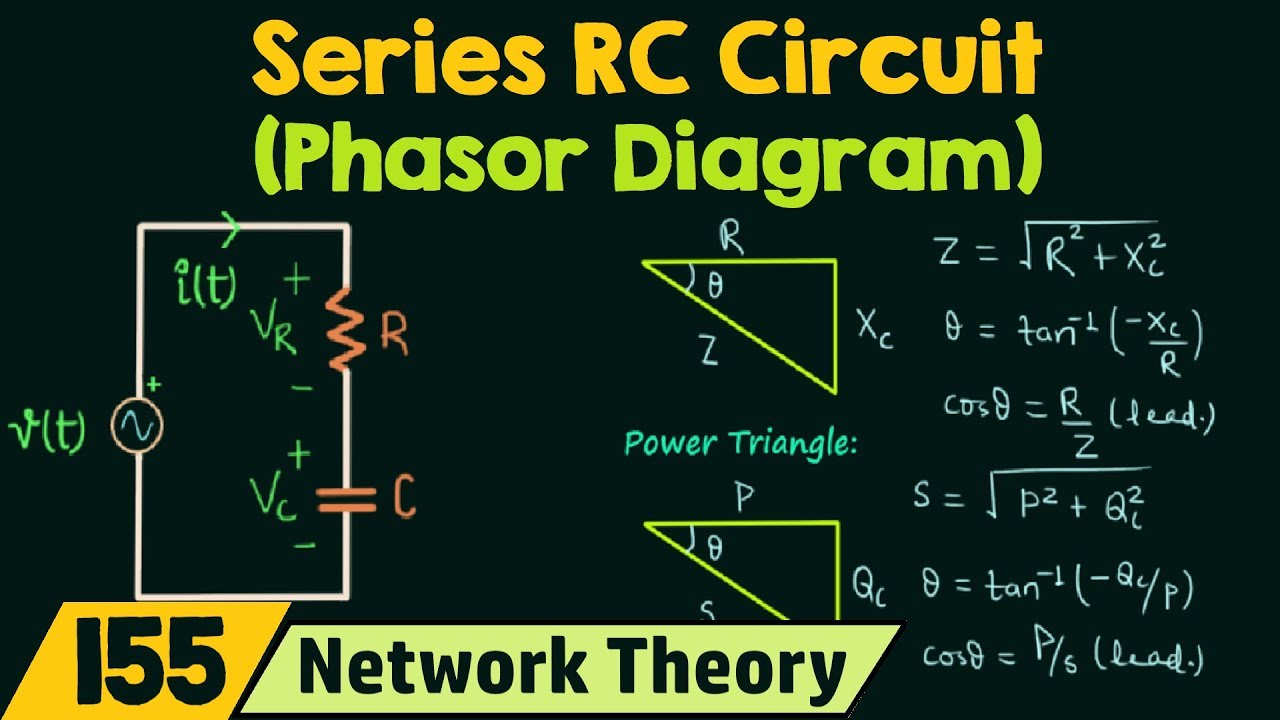
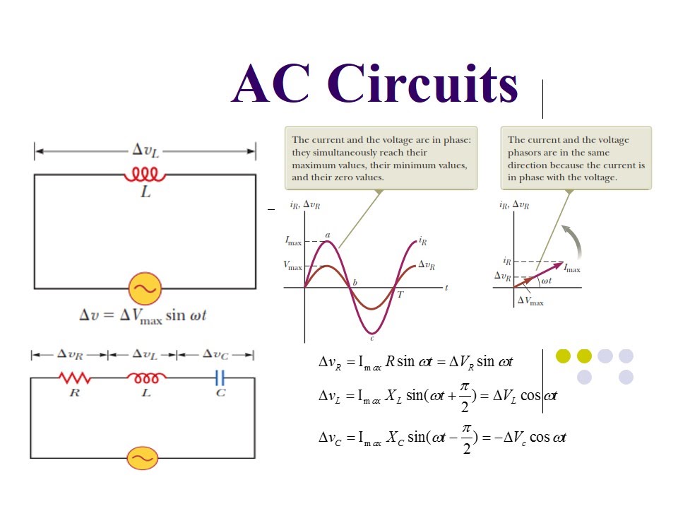
In phasor analysis, a sinusoidal voltage v(t) = Vm*cos(ωt + θ) is represented by a phasor V = Vm∠θ. Here, Vm is the magnitude of the phasor, representing the peak value of the sinusoidal voltage, and θ is the phase angle, representing the initial phase shift of the sinusoid. This compact representation carries all the essential information about the sinusoidal quantity. Similarly, sinusoidal currents are also represented as phasors. By using phasors, we can analyze circuits using complex numbers and impedance, significantly simplifying the process.
Phasor analysis offers several advantages. First, it simplifies calculations by converting differential equations into algebraic equations. Second, it provides a clear visualization of phase relationships between different signals in the circuit. Third, it facilitates the analysis of complex circuits with multiple sources and components.
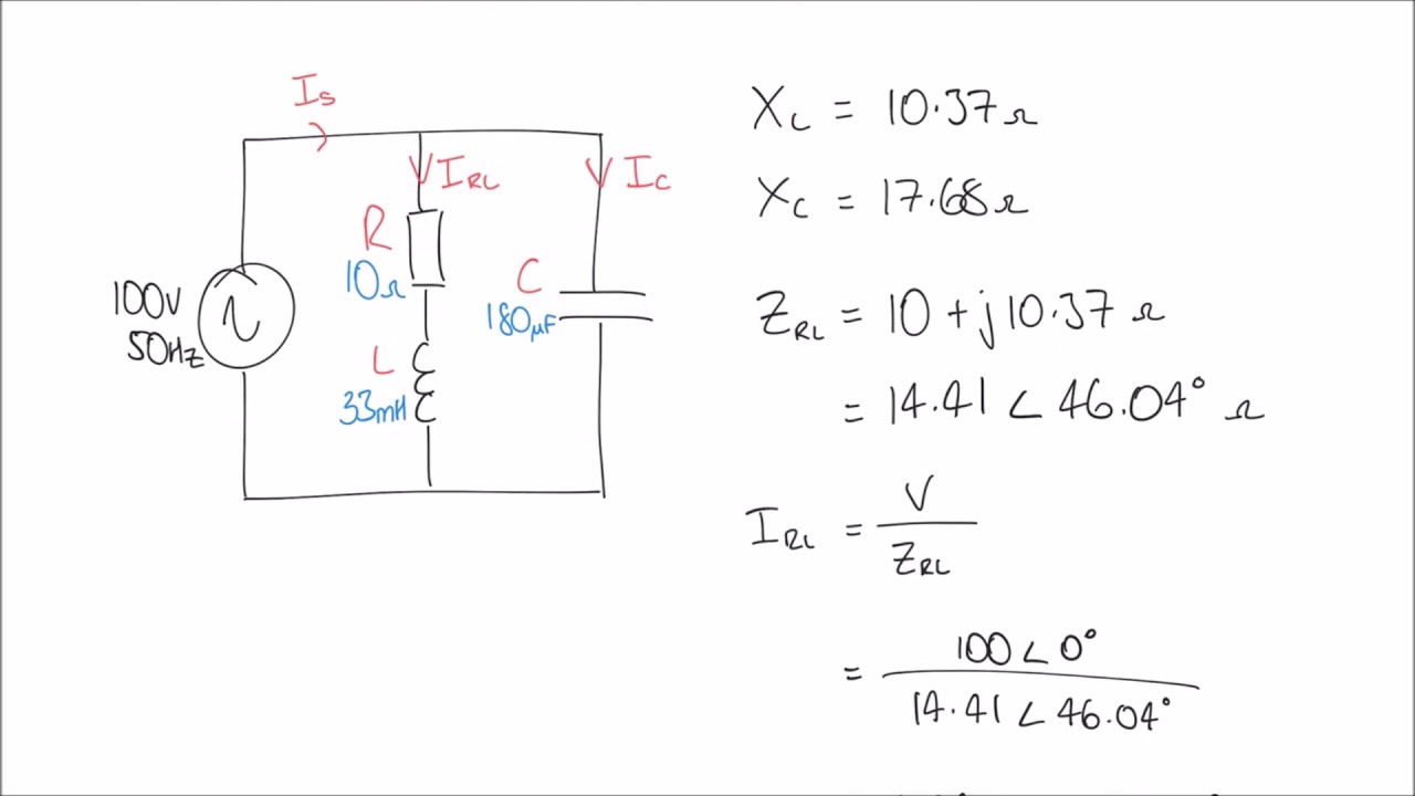
To implement phasor analysis, convert all sinusoidal sources to phasor form. Express impedances of components like resistors, capacitors, and inductors in terms of complex impedance. Then, apply Kirchhoff's laws to the phasor-domain circuit and solve for the unknown phasor voltages and currents. Finally, convert the phasor results back to the time domain to obtain the actual sinusoidal waveforms.
Advantages and Disadvantages of Phasor Analysis
| Advantages | Disadvantages |
|---|---|
| Simplifies AC circuit analysis | Primarily applicable to steady-state analysis at a single frequency |
| Reduces complex differential equations to algebraic equations | Not suitable for transient analysis |
| Provides clear visualization of phase relationships | Requires understanding of complex numbers |
Best practices for using phasor analysis include ensuring all sources operate at the same frequency, correctly representing impedances in the phasor domain, and verifying results by checking Kirchhoff's laws.
Real-world examples of phasor analysis application include analyzing power systems, designing filters, and understanding the behavior of resonant circuits.
Common challenges in phasor analysis involve dealing with complex impedances and correctly converting between the time and phasor domains. Solutions include using complex number calculators and carefully tracking phase angles.
Frequently asked questions about phasor analysis cover topics such as the difference between phasors and vectors, how to represent different types of impedances in the phasor domain, and how to handle circuits with multiple frequencies.
Tips and tricks for phasor analysis include using software tools for complex number calculations and visualizing phasors graphically to understand their relationships.
In conclusion, phasor analysis offers a powerful and efficient method for analyzing AC circuits. By transforming complex differential equations into simpler algebraic ones, it simplifies calculations and provides a clearer understanding of circuit behavior. Mastering this technique is essential for anyone working with AC circuits, from electrical engineers designing power systems to hobbyists building electronic projects. Embracing phasor analysis empowers you to efficiently analyze and design complex AC circuits, opening doors to a world of electrical innovation. So ditch the complicated calculus, grab your phasor compass, and start conquering the world of AC circuits today!
Ndr tv heute abend whats on tonight your guide to german tv
Whats the moon doing tonight in india your lunar guide
Unlocking the value exploring the fifa 23 messi card price


